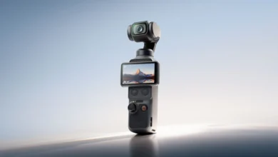
Decoding the Micro-Mechanics and Marketing of Modern Camera Image Stabilization Systems

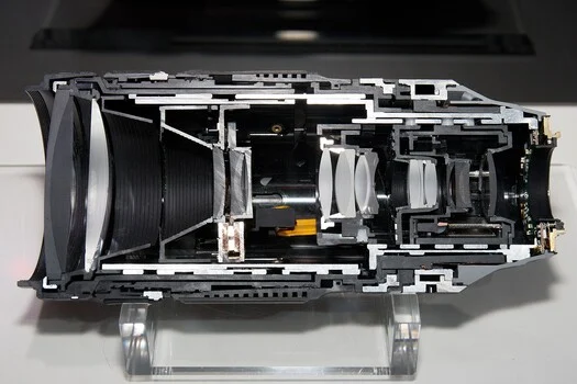
Tilt a 600mm telephoto lens by a mere tenth of a degree—an angular displacement virtually imperceptible to the human hand—and the optical image it projects slides approximately one millimeter across the digital camera sensor. In the architecture of modern photography, nearly every stabilization mechanism exists solely to intercept and cancel that single millimeter of drift while the mechanical or electronic shutter remains open. Whether achieved by laterally translating an internal element of optical glass or by magnetically levitating the entire imaging sensor, these systems represent marvels of micro-engineering. However, understanding how different stabilization technologies operate exposes why the stop-count performance metrics printed on camera retail boxes remain notoriously difficult to compare directly across brands and generations.
Inside the Optical Core: Lens-Based Stabilization Systems
Optical image stabilization goes by a constellation of proprietary acronyms across the photographic industry: Canon utilizes Optical Image Stabilizer (IS), Nikon relies on Vibration Reduction (VR), Sony employs Optical SteadyShot (OSS), Sigma calls its system Optical Stabilizer (OS), Tamron uses Vibration Compensation (VC), and Panasonic brands its technology as Optical Image Stabilizer (O.I.S.). Despite the diverse marketing nomenclature, the underlying physics remain uniform. A designated cluster of internal lens elements, known as the correction group, is driven perpendicularly relative to the central optical axis. By dynamically bending the light path by microscopic margins, the projection system walks the image back to its precise pre-tremor coordinates, ensuring that identical scene details map onto the exact same pixels throughout the duration of the exposure.
The imperative to move originates from a microscopic gyroscope—specifically, a microelectromechanical systems (MEMS) angular velocity sensor small enough to sit on a compact circuit board adjacent to the lens electronic contacts. This sensor does not track absolute pointing coordinates; rather, it measures rotational velocity. The internal processor integrates this angular speed over time to calculate the spatial drift of the image. This operational distinction introduces a fundamental engineering hurdle: a gyroscope’s raw output signal is prone to continuous low-frequency drift. Mitigating this sensor drift represents one of the primary physical constraints governing the maximum exposure duration a stabilization system can reliably hold.
While traditional optical stabilization shifts solid glass elements, alternative engineering approaches exist. Broadcast television lenses and specialized stabilized binoculars frequently employ a vari-angle prism. This system consists of a flexible bellows filled with a high-refractive-index liquid, sealed securely between two parallel glass plates. By dynamically altering its internal wedge angle, the prism steers the optical axis, a mechanism capable of dampening a broader frequency band of vibrations than a standard moving glass group. Because still cameras do not utilize vari-angle liquid prisms, modern consumer photography relies almost exclusively on two competing paradigms: moving lens groups and moving sensor carriages.
The physical actuation is typically handled by voice coil motors, utilizing the identical electromagnetic principles that drive the cone of an audio loudspeaker. By introducing precise electrical current into a coil of wire situated within the magnetic field of a permanent magnet, engineers generate directional force. Tamron, for instance, implements a three-coil arrangement in its VC units, where the stabilizing element rides on a trio of ceramic or metallic balls to minimize mechanical friction. High-precision position sensors constantly monitor the exact physical placement of the group, feeding telemetry back to the processor to establish a closed-loop correction circuit rather than relying on blind algorithmic adjustments.
A standard gyroscope, however, possesses a critical perceptual blind spot: it detects rotation exclusively. Translating the camera body in a strictly linear direction without any rotational tilt produces a net-zero reading from the gyro, even though the projected image has physically shifted across the focal plane. Canon addressed this vulnerability in 2009 with the introduction of Hybrid IS, debuted in the EF 100mm f/2.8L Macro IS USM lens. By integrating an acceleration sensor alongside traditional gyroscopes, the system gained the capability to counteract linear, sideways translation—a type of physical displacement that becomes the dominant source of blur during close-up macro photography.
Sensor-Shift Architecture: Floating the Imaging Plane on Magnets
In-body image stabilization (IBIS) shifts the engineering focus away from the lens assembly entirely, opting instead to manipulate the imaging target. The digital sensor is securely mounted onto a specialized mechanical carriage that floats freely between an array of permanent magnets and electromagnetic coils. This carriage is engineered to remain perfectly flat while retaining lateral mobility across the two-dimensional plane of the image sensor. When engineering teams, such as those at Olympus, detail their IBIS architecture, they describe carrier assemblies riding on ceramic bearings measuring less than a millimeter in diameter, maintained parallel to tolerances of mere thousandths of a millimeter during active translation.
Camera marketing materials routinely boast of five-axis stabilization, a numerical claim that is technically accurate despite the physical stage possessing only three primary degrees of translational and rotational freedom. Pitch and yaw—the vertical and horizontal tilts characteristic of standard handheld camera shake—are actively neutralized by sliding the sensor linearly across the image plane. Roll, defined as rotational twisting around the central optical axis caused by wrist rotation, is counteracted by opposing electromagnetic coils that rotate the entire sensor carriage. Finally, horizontal and vertical linear shifts use the exact same sliding mechanisms deployed for pitch and yaw. Consequently, three physical degrees of freedom successfully combine to neutralize five distinct vectors of physical camera movement.
Roll is uniquely troublesome because it is an axis that lens-based stabilization cannot influence. Shifting an internal lens group can translate an image linearly across the frame, but it cannot rotate it. Only a rotating sensor carriage or post-processing software can correct for roll blur. Furthermore, roll behaves in a manner that evades standard optical evaluations. Under the mathematical parameters defined by the Camera and Imaging Products Association (CIPA) testing protocols, roll blur is entirely independent of focal length. Instead, it scales directly with distance from the center of the frame. Consequently, roll-induced blur is theoretically zero at the exact center of the picture and reaches its maximum severity at the extreme corners—approximately 13 millimeters out from the center in a full-frame 35mm format at the standard 60% image height measurement checkpoint. A camera lacking effective roll correction may produce deceptively sharp imagery in the central composition while displaying pronounced smearing at the periphery.
While the two linear shift axes have negligible impact at normal or infinity shooting distances, their importance scales exponentially in macro photography. When focusing at infinity, a lateral shift of the camera body by one millimeter produces virtually unmeasurable image degradation. However, at a 1:1 macro reproduction ratio, that exact same millimeter of physical sway displaces the projected image by a full millimeter across a sensor measuring only 24 millimeters in vertical height. For photographers engaged in handheld macro work, shift-axis stabilization performs the heavy lifting, explaining why specialized close-up systems incorporate dedicated linear accelerometers into their sensor-stabilization pipelines.
The Synergy of Combined Lens and Sensor Stabilization
Recognizing the limitations inherent to operating either system in isolation, major optical manufacturers developed cooperative stabilization protocols. Canon terms this Coordinated Control IS, OM System utilizes Sync IS, Panasonic implements Dual I.S., and Nikon refers to the technology as Synchro VR. In these configurations, the camera body and the attached lens cease operating as independent actors, establishing a high-speed digital communication channel across the lens mount to divide the workload and prevent redundant corrections for identical shake vectors.
The primary operational advantage of this cooperative approach becomes apparent when utilizing long focal lengths. Image displacement resulting from angular tilt is directly proportional to focal length: a tenth of a degree of pitch displaces the projected image by approximately 0.04 millimeters at a 24mm focal length, but surges to roughly 1 millimeter of displacement at 600mm. A moving sensor carriage must physically travel across this distance to compensate, quickly exhausting the available clearance within the clean imaging circle projected by the lens. Conversely, a correction group embedded deep within a telephoto lens possesses significant optical leverage; minute physical movements of the internal lens glass swing the projected image across vast distances. Thus, the lens absorbs large-scale angular corrections, while the sensor carriage handles fine positioning adjustments, roll, and linear shift.
Published manufacturer specifications underscore the efficacy of this division of labor. The OM System OM-1 Mark II boasts up to 8.5 EV steps of stabilization performance using body-based stabilization alone, measured in conjunction with the M.Zuiko Digital ED 12-40mm f/2.8 PRO II lens at a 40mm focal length (equivalent to 80mm in full-frame terms). Crucially, the system maintains that same 8.5 EV rating when utilizing Sync IS paired with the massive M.Zuiko Digital ED 150-400mm f/4.5 TC1.25x IS PRO lens at a 150mm setting (300mm equivalent). Maintaining identical stop-ratings while quadrupling the focal length illustrates the primary engineering rationale for pairing optical and sensor-shift systems. Nikon’s metrics follow a similar progression: the NIKKOR Z 600mm f/4 TC VR S is rated at 5.0 stops independently, rising to 5.5 stops when mounted on a compatible camera body supporting Synchro VR.
Anatomy of the CIPA Standard and Performance Ratings
The stop-count figures published on product specification sheets are not arbitrary marketing inventions; rather, they are derived from rigorous testing protocols established by the Camera and Imaging Products Association (CIPA). The testing methodology subjects the camera equipment to demanding evaluation procedures. The camera is securely bolted to a certified vibration simulator that replays a standardized 32-second recording of authentic human hand tremor, sampled at a frequency of 500 Hz. The specific waveform applied during testing depends on the combined weight of the camera body and lens: one specific motion profile is utilized for total masses under 400 grams, another for assemblies weighing 600 grams and above, and a dual-waveform protocol for intermediate weights.
During testing, the camera photographs a standardized calibration chart featuring high-contrast black and white edges positioned at a distance equal to 20 times the 35mm-equivalent focal length. The system captures 200 or more frames at varying shutter speeds with stabilization fully operational. A baseline control run of at least ten frames is captured with the vibration rig deactivated and stabilization switched off to quantify the inherent optical degradation introduced by the camera and lens independent of human motion. The resulting blur is quantified across each edge, averaged mathematically, and translated into a stop rating representing how many stops of shutter speed a photographer can sacrifice before the average blur crosses a predefined tolerance threshold. Final performance metrics are rounded to the nearest half-stop.
The underlying performance threshold is where cross-brand comparability frequently breaks down. The legacy 2015 iteration of the CIPA testing protocol subjected cameras exclusively to yaw and pitch vibrations, evaluated sharpness solely at the center of the frame, and deemed an image acceptable provided blur remained beneath 63 micrometers. The updated 2024 CIPA revision substantially tightened this tolerance threshold to 20 micrometers, integrated a roll vibration waveform into the mechanical shake profile, and introduced a secondary measurement checkpoint positioned at 60% image height toward the periphery of the frame.
Crucially, these testing parameters are not uniformly applied. The three rotational waveforms are executed concurrently during every measurement cycle. However, the peripheral 60% metric is optional—recorded when a manufacturer seeks to explicitly highlight corner stabilization performance and omitted when peripheral data cannot be acquired cleanly. CIPA explicitly notes in its official standards documentation that tightening the evaluation threshold alters measured stop counts, and that separating three rotational components rather than two increases technical difficulty, likely reducing the overall stop claims a camera can achieve. Consequently, testing an identical camera body under the updated 2024 standard versus older protocols yields lower, albeit more realistic, performance numbers.
This evolution is readily observable in contemporary specification sheets. Canon rates the EOS R5 Mark II at up to 8.5 stops at the frame center and up to 7.5 stops at the periphery—a performance metric explicitly quoted for the in-body stabilization unit working in tandem with an optical IS lens. Segmenting performance ratings into central and peripheral values is a direct consequence of the 2024 standard revision. Meanwhile, OM System’s advertised 8.5 EV steps derive from body-only testing at an 80mm equivalent, referencing CIPA conditions without specifying the exact standard release year. These seemingly identical numerical claims describe fundamentally different operational achievements. The largest published performance claim currently listed belongs to the Hasselblad X2D II 100C, featuring a specification sheet citing 10 stops at the image center and 8 stops at the edges, measured internally using the XCD 3.5/120 Macro lens. Altering the lens choice, focal length, or testing standard invalidates direct numerical comparisons.
Furthermore, several critical performance vectors remain entirely excluded from CIPA standardized ratings. Linear shift correction falls outside the scope of the standard; manufacturers making performance claims for axes other than yaw, pitch, and roll must label those figures as proprietary measurements derived from non-conforming test methodologies. Electronic and hybrid stabilization systems are governed by entirely separate documentation standards. Consequently, when a camera simultaneously advertises an eight-stop performance rating and five-axis stabilization, the stated stop count describes rotational axis compensation exclusively, rather than all five physical degrees of freedom.
These figures do not represent fraudulent marketing; rather, they reflect standardized laboratory outputs generated by mechanical rigs reproducing averaged human tremor profiles under controlled optical conditions. Human operators introduce variables such as heartbeats, muscle fatigue, and unbraced postures. Photographers should generally anticipate achieving performance metrics one to two stops shy of headline figures during field conditions, treating any excess stability as a situational bonus.
Operational Limitations: What Stabilization Cannot Accomplish
Despite sophisticated engineering, image stabilization remains bound by strict physical limitations. Most notably, stabilization systems cannot freeze subject motion. Activating stabilization allows a photographer to capture a static scene at slow shutter speeds, but photographing a moving subject—such as a running child—at 1/8th of a second with a stabilized 200mm lens will result in a razor-sharp background juxtaposed against a heavily motion-blurred subject. Every stop of stabilization gained translates strictly to increased exposure latitude for camera stability, not subject motion control. No amount of optical or sensor-shift compensation can replace a shutter speed calibrated to match the dynamic movement within the frame.
Tripods introduce an entirely separate operational complication. When a camera is securely locked down on a heavy tripod, environmental hand shake is eliminated. An active stabilization system hunting for micro-movements across a static platform can mistakenly interpret minor electronic noise or rigid anchoring forces as physical vibration, actively injecting artificial blur into the exposure. Consequently, equipment manuals—such as Sony’s technical operation guides—explicitly advise deactivating SteadyShot when utilizing a tripod. While advanced telephoto lenses and modern camera bodies increasingly feature automated tripod detection algorithms capable of identifying locked-down states and safely idling stabilization routines, photographers must consult specific equipment documentation rather than relying on generalized assumptions.
Panning introduces yet another distinct operational requirement. A stabilization mechanism functioning in standard mode will actively resist a deliberate horizontal or vertical sweep across a moving subject, treating the deliberate camera movement as undesirable shake. To counter this, manufacturers incorporate specialized operational modes. Canon’s IS Mode 2 automatically detects panning movements and deactivates stabilization along the panning axis while maintaining vertical correction, whereas Mode 3 delays stabilization activation until the precise moment of exposure to prevent viewfinder lag during tracking sequences. Competing manufacturers offer equivalent horizontal and vertical panning settings, and modern automated algorithms increasingly identify panning gestures dynamically.
Video recording introduces an additional computational layer on top of optical and sensor-shift correction, invariably exacting a toll in available pixels. Electronic image stabilization (EIS) operates by aggressively cropping into the native sensor area and dynamically shifting individual output frames within that digital safety margin. Sony’s operational documentation explicitly warns that the effective angle of view narrows significantly when Active mode is engaged, while more aggressive settings like Dynamic Active further magnify the digital crop and upscale pixels to maintain output resolution. This optical margin is the unavoidable price of digital stabilization; a native 24mm lens operating under heavy electronic stabilization no longer behaves as a true 24mm optic. Furthermore, on sensors exhibiting prominent rolling shutter artifacts, stabilization software may warp individual frames to counteract geometric skew, introducing subtle visual distortions when algorithmic estimations fail.
Practical Methodology for Field Evaluation
For working photographers, navigating conflicting manufacturer specifications requires moving past headline figures and closely evaluating the technical footnotes: verifying the specific lens utilized, the focal length tested, the governing CIPA standard year, and whether metrics reflect central or peripheral performance. The most reliable performance metric is empirical field testing tailored to individual shooting styles. Photographers should adopt their standard physical bracing posture and capture test sequences of ten frames at progressively challenging shutter speeds—such as 1/60s, 1/30s, 1/15s, and 1/8s—subsequently evaluating the percentage of sharp frames surviving at 100% magnification.
This calculated hit rate constitutes an individualized operational rating. While it rarely aligns with the idealistic figures printed on retail packaging, empirical testing provides the only reliable baseline for performance when ambient light fades and critical photographic moments hang in the balance.
Related posts: